PROGRAMINO IDE - Programino-Lab


Turn your Arduino™ board into a measuring station for your laboratory.
- Voltage autoscale.
- Logger function.
- Serial communication
- Analog gauges (analog input).
- Digital mutlimeter (analog input).
- Analog plotter (analog input).
- LEDs (digital input).
- Digital Button (digital port).
- Analog slider (analog port - PWM).
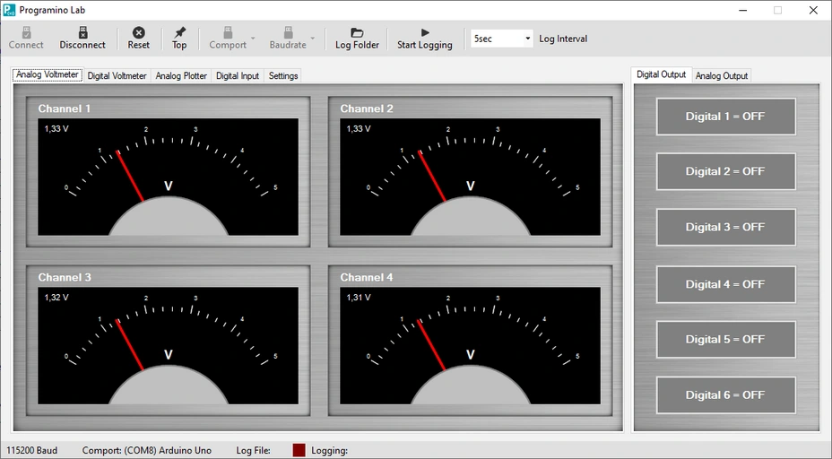
Analog Voltmeter
- The four analog voltmeters can be used as multi-channel voltmeters.
- The display has an autoscale function.
- The analog inputs A0, A1, A2 and A3 are used for this purpose (Arduino UNO).
- However, you can change the inputs to other pins in the firmware.
Digital Output
- You can use the buttons on the right side for digital output.
- In the firmware, the digital outputs 8, 9, 10, 11, 12 and 13 are used for this function.
- You can change the outputs in the firmware for your board.
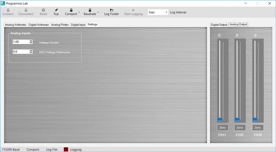
Analog Output
- With the PWM controllers you can output analog (PWM) values at pins 3, 5 and 6 (Arduino UNO).
- You can use them to control a motor driver, for example.
Digital Voltmeter
- The digital voltmeter is similar to the analog voltmeter, but still has a bargraph display.
Analog Plotter
- The analog plotter records up to 4 channels.
- It has an Autoscal function.
Digital Inputs
- The LED indicators allow you to visually view the status of digital inputs.
- The firmware uses the Arduino™ inputs A4, A5, 2, 4 and 7 (Arduino™ UNO) for this application.
- You can also customize these individually.
Settings
Voltage Divider: Here you can specify the divider of the external voltage divider for the analog inputs.
ADC Voltage Reference: Here you can specify the reference voltage of the ADC.
Common voltages are 1, 1.1, 3.3 or 5 volts.
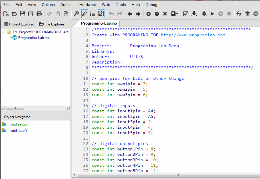
Download the Programino Lab firmware to your Arduino™ board.
The firmware is located under "Programino Examples\Programino-Lab".
Now you can play with the Programino Lab!
Example Code: